|
- Fully compatible with JTAGICE mkII, easy to use, stable and reliable
- Identified as JTAGICE mkII in AVRStudio, high speed debugging and programming
- Firmware is upgradable to Support Future Devices
- Automatic Upgrade
- AVR Studio 4/5/6, WINAVR(GCC) or IAR is used as front-end software
- Supports the program files generated by ICCAVR, CVAVR, IAR
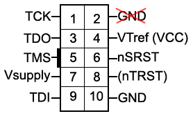
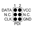
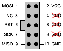
- Supports debugging and programming of all AVR and AVR32 devices with JTAG, PDI, debugWIRE Interface
Refer to AVR Studio 6, the following devices are supported:
| AVR UC3 |
| AT32UC3A0128 AT32UC3A0256 AT32UC3A0512 AT32UC3A1128 AT32UC3A1256 AT32UC3A1512 AT32UC3A3128 AT32UC3A3128S AT32UC3A3256 AT32UC3A3256S AT32UC3A364 AT32UC3A364S AT32UC3A4128 AT32UC3A4128S AT32UC3A4256 AT32UC3A4256S AT32UC3A464 AT32UC3A464S AT32UC3B0128 AT32UC3B0256 AT32UC3B0512 AT32UC3B064 AT32UC3B1128 AT32UC3B1256 AT32UC3B1512 AT32UC3B164 AT32UC3C0128C AT32UC3C0256C AT32UC3C0512C AT32UC3C064C AT32UC3C1128C AT32UC3C1256C AT32UC3C1512C AT32UC3C164C AT32UC3C2128C AT32UC3C2256C AT32UC3C2512C AT32UC3C264C AT32UC3L0128 AT32UC3L016 AT32UC3L0256 AT32UC3L032 AT32UC3L064 ATUC128D3 ATUC128D4 ATUC128L3U ATUC128L4U ATUC256L3U ATUC256L4U ATUC64D3 ATUC64D4 ATUC64L3U ATUC64L4U |
| AVR Mega |
| AT90CAN128 AT90CAN32 AT90CAN64 AT90PWM1 AT90PWM161 AT90PWM216 AT90PWM2B AT90PWM316 AT90PWM3B AT90PWM81 AT90USB1286 AT90USB1287 AT90USB162 AT90USB646 AT90USB647 AT90USB82 ATA5702M322 ATA5781 ATA5782 ATA5783 ATA5790 ATA5790N ATA5795 ATA5831 ATA5832 ATA5833 ATA6285 ATA6286 ATA6612C ATA6613C ATA6614Q ATA6616C ATA6617C ATA664251 ATmega128 ATmega1280 ATmega1281 ATmega1284 ATmega1284P ATmega1284RFR2 ATmega128A ATmega128RFA1 ATmega128RFR2 ATmega16 ATmega162 ATmega164A ATmega164P ATmega164PA ATmega165A ATmega165P ATmega165PA ATmega168 ATmega168A ATmega168P ATmega168PA ATmega168PB ATmega169A ATmega169P ATmega169PA ATmega16A ATmega16HVA ATmega16HVB ATmega16HVBrevB ATmega16M1 ATmega16U2 ATmega16U4 ATmega2560 ATmega2561 ATmega2564RFR2 ATmega256RFR2 ATmega32 ATmega324A ATmega324P ATmega324PA ATmega325 ATmega3250 ATmega3250A ATmega3250P ATmega3250PA ATmega325A ATmega325P ATmega325PA ATmega328 ATmega328P ATmega329 ATmega3290 ATmega3290A ATmega3290P ATmega3290PA ATmega329A ATmega329P ATmega329PA ATmega32A ATmega32C1 ATmega32HVB ATmega32HVBrevB ATmega32M1 ATmega32U2 ATmega32U4 ATmega48 ATmega48A ATmega48P ATmega48PA ATmega48PB ATmega64 ATmega640 ATmega644 ATmega644A ATmega644P ATmega644PA ATmega644RFR2 ATmega645 ATmega6450 ATmega6450A ATmega6450P ATmega645A ATmega645P ATmega649 ATmega6490 ATmega6490A ATmega6490P ATmega649A ATmega649P ATmega64A ATmega64C1 ATmega64HVE2 ATmega64M1 ATmega64RFR2 ATmega8 ATmega8515 ATmega8535 ATmega88 ATmega88A ATmega88P ATmega88PA ATmega88PB ATmega8A ATmega8HVA ATmega8U2 |
| AVR Tiny |
| ATtiny13 ATtiny13A ATtiny1634 ATtiny167 ATtiny2313 ATtiny2313A ATtiny24 ATtiny24A ATtiny25 ATtiny26 ATtiny261 ATtiny261A ATtiny4313 ATtiny43U ATtiny44 ATtiny441 ATtiny44A ATtiny45 ATtiny461 ATtiny461A ATtiny48 ATtiny828 ATtiny84 ATtiny841 ATtiny84A ATtiny85 ATtiny861 ATtiny861A ATtiny87 ATtiny88 |
| AVR Xmega |
| ATxmega128A1 ATxmega128A1U ATxmega128A3 ATxmega128A3U ATxmega128A4U ATxmega128B1 ATxmega128B3 ATxmega128C3 ATxmega128D3 ATxmega128D4 ATxmega16A4 ATxmega16A4U ATxmega16C4 ATxmega16D4 ATxmega16E5 ATxmega192A3 ATxmega192A3U ATxmega192C3 ATxmega192D3 ATxmega256A3 ATxmega256A3B ATxmega256A3BU ATxmega256A3U ATxmega256C3 ATxmega256D3 ATxmega32A4 ATxmega32A4U ATxmega32C3 ATxmega32C4 ATxmega32D3 ATxmega32D4 ATxmega32E5 ATxmega384C3 ATxmega384D3 ATxmega64A1 ATxmega64A1U ATxmega64A3 ATxmega64A3U ATxmega64A4U ATxmega64B1 ATxmega64B3 ATxmega64C3 ATxmega64D3 ATxmega64D4 ATxmega8E5 |
|