Overview
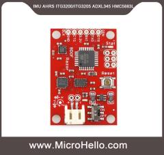
The 9DOF Razor IMU incorporates three sensors - an ITG-3200 (MEMS triple-axis gyro), ADXL345 (triple-axis accelerometer), and HMC5883L (triple-axis magnetometer) - to give you nine degrees of inertial measurement. The outputs of all sensors are processed by an on-board ATmega328 and output over a serial interface. This enables the 9DOF Razor to be used as a very powerful control mechanism for UAVs, autonomous vehicles and image stabilization systems.
The board comes programmed with the 8MHz Arduino bootloader (stk500v1) and some example firmware that demos the outputs of all the sensors. Simply connect to the serial TX and RX pins with a 3.3V FTDI Basic Breakout, open a terminal program to 57600bps and a menu will guide you through testing the sensors. You can use the Arduino IDE to program your code onto the 9DOF, just select the ‘Arduino Pro or Pro Mini (3.3v, 8mhz) w/ATmega328’ as your board.
The 9DOF operates at 3.3VDC; any power supplied to the white JST connector will be regulated down to this operating voltage - our LiPo batteries are an excellent power supply choice. The output header is designed to mate with our 3.3V FTDI Basic Breakout board, so you can easily connect the board to a computer’s USB port. Or, for a wireless solution, it can be connected to the Bluetooth Mate or an XBee Explorer.
Features
- 9 Degrees of Freedom on a single, flat board:
- ITG-3200 - triple-axis digital-output gyroscope
- ADXL345 - 13-bit resolution, ±16g, triple-axis accelerometer
- HMC5883L - triple-axis, digital magnetometer
- Outputs of all sensors processed by on-board ATmega328 and sent out via a serial stream
- Autorun feature and help menu integrated into the example firmware
- Output pins match up with FTDI Basic Breakout, Bluetooth Mate, XBee Explorer
- 3.5-16VDC input
- ON-OFF control switch and reset switch
- 1.1" x 1.6" (28 x 41mm)
-
-


Standard calibration(标准校准)
It might be good to power up the Razor a few minutes before calibration, so the sensors can warm up. Calibrating the sensors the first time can be a little tricky, but let’s go:
- Open Arduino/Razor_AHRS/Razor_AHRS.ino using Arduino and find the section "USER SETUP AREA" / "SENSOR CALIBRATION". This is where you put the calibration values later.
- Connect the Razor AHRS to your computer, set the correct serial port in Arduino and open the Serial Monitor.
-
If you didn’t change the firmware defaults, you should see lots of output like this:
#YPR=-155.73,-76.48,-129.51
-
Set the firmware output mode to calibration by sending the string #oc. You should now see output like this:
accel x,y,z (min/max) = -5.00/-1.00 25.00/29.00 225.00/232.00
- Calibrating the accelerometer:(加速度校准)
- We'll try to find the minimum and maximum output values for the earth gravitation on each axis. When you move the board, move it real slowly, so the acceleration you apply to it is as small as possible. We only want pure gravity!
- Take the board and point straight down with the x-axis (remember: x-axis = towards the short edge with the connector holes). While you do that, you can see the x-maximum (the second value) getting bigger.
- Hold the board very still and reset the measurement by sending #oc again.
- Now carefully tilt the board a little in every direction until the value does not get bigger any more and write down the x-maximum value.
- Do the same thing for the opposite side (x-axis pointing up) to get the x-minimum: bring into position, send #oc to reset measurement, find x-minimum value and write it down.
- Do the same thing for the z-axis (down and up) and the y-axis (right and left).
- If you think you messed up the measurement by shaking or moving the board too fast, you can always reset by sending #oc.
- You should now have all the min/max values. Put them into Razor_AHRS.ino.
- NOTE: You have to be really careful when doing this! Even slightly tapping the board with the finger messes up the measurement (try it!) and leads to wrong calibration. Use #oc very often and double check your min/max values)
-
Calibrating the magnetometer:(磁场校准)
-
Calibrating the gyroscope:(陀螺仪校准)
- Done :)
Extended magnetometer calibration(磁场扩展计校准)
The standard magnetometer calibration only compensates for hard iron errors, whereas the extended calibration compensates for hard andsoft iron errors. Still, in both cases the source of distortion has to be fixed in the sensor coordinate system, i.e. moving and rotating with the sensor.
- To start calibrating, put the sensor in the magnetic environment where it will be used later - e.g. in the exact spot on your headphones, if you need to to head-tracking for audio applications (headphones have strong magnets, the less you move the sensor after calibrating, the better your results will be; you should also think about putting some dummy material between the ear cups to bring them in normal hearing position).
- Quit all applications that read from the sensor (e.g. Serial Monitor, Processing test sketch, …) and run the Processing magnetometer calibration sketch located in in Processing/Magnetometer_calibration. In fact, you have to install the EJML library first, else the sketch won’t run. How to do that? Have a look at the NOTE at the top of Magnetometer_calibration.pde.
-
Try to rotate the sensor in a way so that you cover all orientations so you produce dots that more or less evenly cover the sphere.
-
In a mostly undistorted environment this could look something like this:

-
Hit SPACE and watch the Processing console - you’ll find some lines of code that you have to put into the firmware under "USER SETUP AREA" / "SENSOR CALIBRATION" and you’re done.
The collected data (the dots) are also written to a file magnetom.float in the sketch folder. Now in case you own Matlab, underMatlab/magnetometer_calibration you’ll find a script called magnetometer_calibration.m that uses this file and produces some plots for you, so you can visually check the calibration.
Ellipsoid fit and corrected values:


Another calibration example: Soft iron gives a sphere scaled and distorted into an ellipsoid.
Another calibration example: Hard iron gives an offset sphere.